What is XCP
XCP is a standard protocol that enables calibration on modern ECU's. Learn how it works here
If you stayed on the automotive industry long enough, you probably have already heard calibration is an important step of ECU development. It allows to fine tune parameters on the ECU so that our sensors, control algorithms, work according to our system requirements. We have discussed how calibration is performed before, in the article Calibration Overview (opens in a new tab), where we discussed the multiple forms of calibration, and even touched on XCP multiple times, as the concepts are tightly related. We also recommend learning about A2L in our article The Basics of A2L Files (opens in a new tab), as the MC-Tools take part of the A2L description to match the ECU configuration of XCP and communicate with the ECU through it.
So, what is XCP (Universal Measurement and Calibration Protocol), and why do we use it? Defined by the ASAM MCD-1 XCP standard, it enables access to the memory inside our ECU's, which means we can measure and calibrate, in theory, any memory range (if we consider memory overlay, of course), via our preferred communication bus (the X in XCP stands for the flexibility of transport layer we can use), with the exception of LIN, which is too slow for XCP. It provides us a way to measure and stimulate variables periodically or via polling, perform memory paging (more on that in a moment), reprogram our ECU, perform project-specific operations (just like we can do via UDS), and even debugging. We see here that some functionalities overlap with UDS (you can check our article UDS Overview (opens in a new tab)), but they are, in fact, very different. Firstly, XCP is a development module, which is available in production. And due to its memory access capabilities, it makes sense, because there isn't a very secure authentication mechanism. Second, the periodic measuring, calibration and memory paging capabilities are way more powerful than those on UDS. Third, XCP is well-establised as the de-facto protocol, used by the MC-Tools. Now, let's take at dive on the XCP protocol.
XCP Events, DAQ and STIM Lists, ODT's and ODT Entries:
DAQ (Data AcQuisition) and STIM (Data STIMulation) lists are at the heart of the XCP protocol. All other resources are pretty transversal to other modules you may find in Autosar, but these are very XCP-specific, and make it extremely useful. To learn them, we'll dive into the four concepts mentioned above:
-
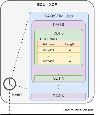
XCP Events - a cyclic function to read and write data. An event on XCP can be associated to one or more DAQ/STIM lists, bringing them to life. The event is defined by the timing, priority, if it handles DAQ, STIM or both, number of DAQ/STIM lists it can handle and the event consistency. The latter defines what the event handles when it gets triggered. There are 3 options: event, meaning it processes all DAQ/STIM lists at once (takes the longest), DAQ/STIM, processing 1 DAQ/STIM list each time the event is triggered, or ODT, handling only 1 ODT at a time. These parameters are all defined on the A2L file, as they are relevant to the MC-Tool.
-
DAQ / STIM Lists - a list of variables to be read from the ECU (DAQ) or written to it (STIM) periodically, according to the event they are associated to. Inside a DAQ/STIM list, there are ODT's. The number of ODT's a DAQ/STIM list can allocate depends on the bus throughput. For example, if you have a very small timing for the number of ODT's you are trying to send/receive on your ECU, it's possible that your bus won't be able send all the ODT's before the next event fires, resulting in a DAQ overload. The configuration of DAQ and STIM lists can be static (defined by compile-time, way faster but no flexibility), where you define all the objects that lead to it (ODT's and ODT entries), and associate them to events, or dynamic (run-time, slow to start but very flexible) through specific XCP commands. The dynamic configuration is handled very efficiently by MC-Tools, maximizing the use of resources.
-
ODT (Object Description Table) - a table of ODT entries. The ODT's are the product you see on the communication bus. Thus, the number of bytes an ODT can allocate is defined by the bus size, usually.
-
ODT Entry - a pair of address and length. Since this value is deterministic, you can, by compile-time, know the size to allocate on the ECU of your DAQ/STIM lists. You may also want to allocate it on the NVRAM, to use the resume mode of XCP. We'll eventually get to it, when we discuss the XCP commands, in a future article. From an XCP perspective, an ODT entry length is defined as AG (Address Granularity), which translates directly to a number of bytes.
Since we have thrown many concepts around, here is a picture to make you understand the relationship between events, DAQ/STIM lists, ODT's and ODT entries:

Relationship between events, DAQ/STIM lists, ODT's and ODT entries
Communication Protocol:
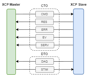
There are two types of messages on XCP: CTO (Command Transfer Object) and DTO (Data Transfer Object). Inside them, there are specific command categories. For CTO messages:
-
CMD (Command) - Send commands to the ECU (via a MC-Tool, for example). A command is always answered by the ECU through a RES or an ERR.
-
RES (Response) - Response sent by the ECU in response to a CMD. The first byte is 0xFF, followed by a command-specific response, which you can find in the XCP specification.
-
ERR (Error) - Error message sent by the ECU, in case a CMD goes wrong. The first byte is 0xFE, followed by an error code, very useful to debug an error.
-
EV (Event) - Event packet sent by the ECU asynchronously, when a specific condition is met. Usually, these conditions are red flags. Some common events are autonomous XCP disconnect by the ECU, in case of a connection timeout, or a DAQ overload (we'll talk about DAQ lists in a moment). The first byte, or packet identifier, is 0xFD.
-
SERV (Service) - Service request made by the ECU. The packet identifier is 0xFC.
Now that we know what DAQ and STIM lists are, the DTO command categories are easy to understand. They transfer DAQ or STIM lists, depending on the direction. In sum, the CTO and DTO messages and their direction can be depicted in the following picture:

CTO and DTO message categories
XCP Message Structure:
Depending on the type of message and the category within it, the XCP protocol will send a different kind of message. But the building blocks are always the same, they are just present or absent according to the kind of message. In the picture below, you can see all the possible fields that can take part in an XCP frame. By analysing each of these fields carefully, we'll know what they mean and in what kinds of commands we find them:
-
Frame Header / Tail - Header and tail of the communication protocol in use. Some options are CAN, FlexRay and Ethernet.
-
PID (Packet Identifier) - Present in CTO messages to specify the type of packet in question (any XCP command, a RES, ERR, EV or SERV).
-
DAQ/STIM - Identifies the DAQ/STIM list being sent. It can be absent if the absolute ODT number is configured to be sent.
-
CTR (Counter) - The ODT index being sent/received. It can be an absolute number (all DAQ/STIM lists share the numeration) or relative to the DAQ/STIM list.
-
Timestamp - Used in DTO packets to identify the timing of the measurement. Its size ranges from 1 to 4 bytes.
-
Data - The CTO parameters or contents of an ODT, in case of a DTO message.

XCP CTO (top) and DTO (bottom) message structure
Communication Modes:
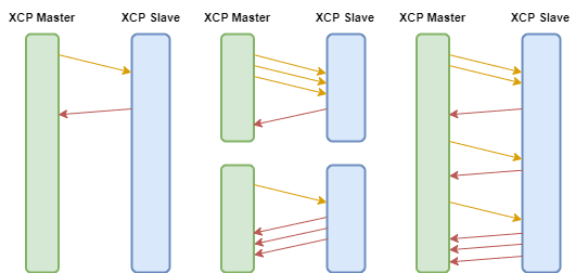
XCP resorts to 3 different communication modes, which defer on the number of commands being sent in each direction:
-
Standard - Each request is followed by a response.
-
Block - This mode has two different configurations, depending on the direction. In case of a master block mode, multiple requests are sent, and a single response is received in the aftermath. In the slave block mode, the opposite is valid, a single request triggers multiple responses.
-
Interleaved - The master and slave can both send multiple requests or responses.

Standard (left), block (middle) and interleaved (right) XCP communication modes
As some closing thoughts, we hope this article helped you understand some of the basics of the XCP protocol, specifically, what it is, why it's so useful in ECU development and the protocol structure. We intentionally left the commands out of this article, in order to maximize the learning potential. They will have their own article in the future, so stay tuned!
Author: Micael Coutinho (opens in a new tab)
References:
- Specification of Module XCP - Autosar Specification (opens in a new tab)
- ASAM MCD-1 XCP - ASAM (opens in a new tab)
© AutosarToday —@LinkedIn