What is J1939
J1939 is a set of protocols that specify a higher-layer for CAN communication in heavy duty vehicles. Learn all about it here
Imagine you leave in a perfect world, where all the communication in every vehicle is standardized and all manufacturers use the same messages (to some degree) in the CAN bus to specify the same data. One can wish, because it will likely not happen. We already get a pretty good agreement between the OEM's with Autosar.
In heavy duty vehicles, though, such vision is not utopian. There is J1939! But, for the 80% of us who never worked in such vehicles, what does it mean? J1939 is a Higher-Layer Protocol (HLP) developed by SAE, that sits on top of the CAN physical layer, and provides standardized communication for all ECU's in heavy duty vehicles, across the OEM's. Isn't life beautiful? So, as promised in our article Diagnostics on Vector CANoe - Part 1 (opens in a new tab), we'll learn about this protocol set today.
Let's dig more about the J1939. As we all know, from our previous studies on CAN, in the article CAN Protocol Overview (opens in a new tab), CAN provides the two lowest layers in the OSI model (physical and link). J1939 contains the other layers on top. Some of its characteristics are:
- Baudrates typically sit between 250k and 500k baud, depending on the type of connector (250k for type 1, 500k for type 2)
- Always uses an extended CAN-ID (29 bits), by using 18 bits to define a PGN (Parameter Group Number), which corresponds to a vehicle parameter. There are also J1939 signals, denominated SPN (Suspect Parameter Numbers)
- Most messages are broadcast, although you can also request data
- Messages with up to 1785 bytes are supported, through the J1939 transport protocol
- Allows a maximum of 40 meters cable length, 30 ECUs in a network and 253 CA's (Controller Applications), where one ECU can manage multiple CA's
- As diesel engines are adopted widely, J1939 is also found among other fields, such as marine, industrial and rail transportation
Now that we know some of its core particularities, let's look at the message format of J1939:

J1939 message format
As you can see by the picture above, the messages from J1939 always contains an extended CAN-ID, where the first 3 bits are the priority, followed by 18 bits of the PGN (Parameter Group Number) and 8 bits for the source address.
Focusing on the PGN, you see there is a bit for reserved, a bit for data page, 8 for the PF (PDU Format, depending if it is smaller than 240 or equal/higher, this specifies if the message is addressable and the PF contains the destination address, or that is a broadcast message and the PS, PDU Specific contains the group extension).
Regarding the SPN, you just witnessed that a single message can contain multiple of them. Each SPN contains an identifier for the CAN signals in the message. They have a variable start position and length. You can use a CAN database (DBC) to learn about 50% of the signals in a heavy duty vehicle, where the rest is OEM-specific. If you have a lot of free time, maybe you can build your own J1939 decoder!
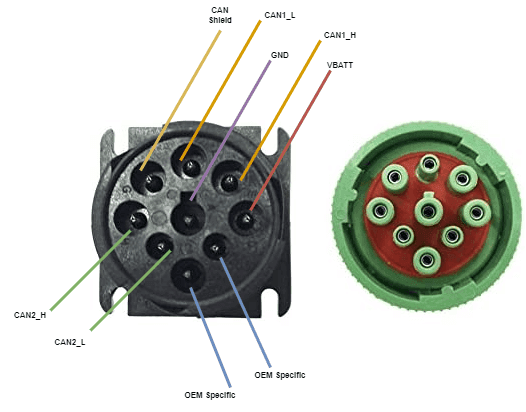
To finish off, we will learn about the J1939 connector. As seen by the picture, you have the two types, 1 (black) and 2 (green). Their difference is the speed. As mentioned before, type 1 cables only allow a maximum 250k baud, while type 2 enable 500k baud. The connector, which can also be called 9-pin deutsch connector, contains the following pinout:

J1939 connector pinout
Through the pinout picture, you can see that the J1939 accommodates 2 CAN connectors, and two pins for OEM-specific stuff, aside from a CAN shield and ground / battery voltages.
Alright, now that you know the basics of J1939, we can wrap this up for today. We hope you enjoyed this article, and see you again soon, when we cover the J1939 transport protocol and its data logging capabilities. Maybe you can consider subscribing to our weekly mailing list, so you don't miss a thing. It's free, and you won't miss a thing!
Author: Micael Coutinho (opens in a new tab)
References:
© AutosarToday —@LinkedIn