CAN-TP Overview
CAN-TP is important to extend the capabilities of CAN, by enhancing the very limited PDU size, making it a crucial part in communication. Learn how it works here
If you read our article CAN Protocol Overview (opens in a new tab), you know one of the biggest limitations of CAN is that you can only send an 8-byte payload at a time. But, as you probably know if you took the time to read our articles regarding UDS (UDS Overview (opens in a new tab) and UDS Frames and NRC Codes (opens in a new tab), which we highly recommend if you want to learn about ECU diagnostics), the frames sent can take a total of bytes way bigger than 8, by sending multiple frames. But how is this performed, how are the fremes segmeted and reconstructed? This is where CAN-TP (CAN Transport Layer) comes in.
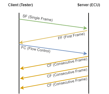
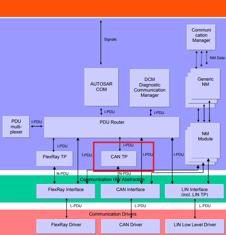
Sitting between the PDUR (PDU Router) and the remainer of the CAN stack, the main purpose of CAN-TP is to segment PDU's bigger than 8 bytes, for each direction. This is achieved creating or parsing the SF (Single Frame), CF (Consecutive Frame), FF (First Frame) and FC (Flow Control) frames. We have already touched up these names a bit in the article UDS Frames and NRC Codes (opens in a new tab). Now, from the CAN-TP perspective:
-
SF (Single Frame) - Contains a message that can fit into a single frame.
-
FF (First Frame) - The first frame of the response, with the initial part of the response and the total response length. This way, the receiver knows more messages are coming.
-
FC (Flow Control) - Configures some parameters that will define how the rest of the messages will be sent. Most notably, there is the ST (Separation Time) Min parameter, which specifies the minimum time distance between each frame and BS (Block Size), the size of each consecutive frame.
-
CF (Consecutive Frame) - Where the remainder of the response is sent by the ECU, according to the parameters specified in the FC frame.
These all come together in UDS like below:

UDS interaction made possible by the CAN-TP frames
These are the only frames CAN-TP cares for. Everything else gets routed to another module (from CAN-IF to PDUR, for example, in case of message reception or the opposite, for transmission). The transport layer is not exclusive of CAN. LIN and FlexRay also contain a transport layer for the same purposes.

CAN-TP connections, as per Autosar specification
Aside from segmenting and reconstructing the PDU's that are thrown to it, CAN-TP also provides functionalities for:
-
Data flow control
-
Detection of segmentation errors
-
Transmission and reception cancelation
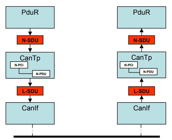
Now, let's mention another important part: what do we need to configure CAN-TP? To connect with the other layers, you need an N-SDU (for CAN-TP) and an L-SDU (for CAN-IF). Each SDU is linked to a CAN-TP connection. Even though this connection can be shared through multiple SDU's, you may not want to do that, as only a single reception / sending per connection is allowed. Obviously, each connection will have its own resources, and they are not shared with each other. They are independent. Lastly, a connection can be half or full-duplex.

CAN-TP communication, as per Autosar specification
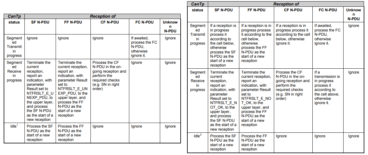
As we mentioned, only 1 sending / reception per connection is allowed at once. So, if more than 1 channel tries to communicate at once, what happens? For this, there are two neat tables that cover about every case, both for half and full-duplex communication. They depend on the current connection status and the type of CAN-TP frame. You can check these edge cases in the tables below:

CAN-TP connection behavior for half (left) and full-duplex (right), as per Autosar specification
Laslty, we'd like to touch on a specific of CAN-TP which is important to other modules, such as UDS and OBD, which is addressing. There are two options for addressing on CAN-TP: physical and functional addressing:
-
Physical Addressing - Used for 1:1 communication. This is used in UDS, for example, for the requests where you want to address a specific ECU. 0x22 (Read Data by Identifier), for example, is one of those cases.
-
Functional Addressing - Used for 1:N communication. In this case, the communication is addressed to all the ECU's in the network. OBD is always performed with functional addressing.
As some finishing thoughts, some modules that notably make use of CAN-TP are DCM (Diagnostic Communication Manager) and DLT (Diagnostic Log and Trace). So, when configuring those modules, make sure to leave this article in the back of your head, as it will for sure be useful. The only thing left to cover are the API's which we'll do someday, but they are not as important. Usually, these are handled by the surrounding layers, so it's very likely you won't deal with them. So, let's leave them for another article. See you next time! Make sure you subscribe our mailing list, so you don't miss a thing.
Author: Micael Coutinho (opens in a new tab)
References:
More from the author
© AutosarToday —@LinkedIn